Thursday, September 27, 2012

PLASMA! --and a homemade flyback transformer!

WARNING! 
SERIOUSLY -- DO NOT attempt to work with ANY high voltage device without the supervision of an experienced person.  I was nearly killed when I was 10 because I did not have such a person.  If you can't read schematics without a cheat sheet, and or if you don't feel you know what you are doing--then you should not be doing it without help!  Electricity can KILL.  And even the power in this jar-capacitor (above) is enough to kill.   High voltage is fun but it is no joke.  The many applications it has are great, but it can cause severe burns, permanent nerve damage, and death.  I am showing these things for example and demonstration purposes only.  I have been working with electronics seriously for over 20 years. I am trained and licensed so I know what I am doing.  DO NOT attempt to play with electricity.  The field is vast and complicated.  So in order to learn you either need to get a good mentor (such as a amateur radio operator), go to school, or both.  ESPECIALLY when it comes to high voltage, as things happen with these kinds of voltages that require extra knowledge and understanding.  BE CAREFUL. 30 volts can kill under the wrong conditions.  If you are a kid getting into electronics, I recommend you start out with a low voltage experiment kit of some kind.  Many awesome kits can be found at Radio Shack and as they did for me, will bring you weeks or even years of enjoyment as well as teach you the basics needed to get to a level where you can be safe working with high voltage gear.  Remember too--it's not just you.  Fire is a serious hazard with nearly any project.  And a carelessly left on or plugged in piece of gear can cause serious harm to a child or pet that comes in contact with it.  Think about your experiment in depth before you do it and take no unnecessary risks.  While it is possible to be self educated in any field, most people including myself need years learning from some kind of teacher to seriously know electronics, it is a very complex and deep subject with many branches.  BE CAREFUL!  I am not responsible for what anyone does with the ideas or information I post on this blog. Attempt all experiments or projects at your OWN RISK.

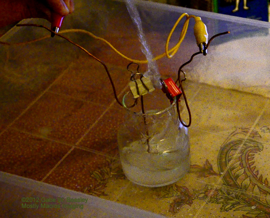
My passion for electronics has been with me longer then my serious interest in photography.  I have studied it on and off for most of my entire life.  This has allowed me to become a licensed Technician class amateur radio operator and build many really awesome devices.  This is a dangerous one--It is simple but can produce high current levels at high voltage.  Here, at least 50kv, 50,000 volts passes between a jumper lead and the top of this high voltage capacitor I made at home (above picture-blue arcs).

This is the most dangerous experiment I have done in recent times.   It is so dangerous I won't post an article on how to complete it on line.  I will say put simply, it's a storage capacitor system that again generate a very high voltage for a moment which is also at a very high current level-as many as 20 or 30 amps!  So many amps here that the entire thing lights up with sparks for a moment when filmed at high speed.  This cannot be seen with the naked human eye.

This is what the camera picked up at the exact moment of contact--the human eye sees this same flash brighter then a camera flash.  In about 1/30th of a second an arc happens inside about 7mm of water that has been saturated with Epsom salt.  This solution produces higher conductivity for the experiment and may add to the light produced.  Under normal circumstances water is pretty conductive and thus electricity will not arc under water.  If one is doing an electrolysis experiment you can see what happens by shorting the terminals under water, they will spark when in contact but only when in direct contact.    Even very high voltage just arks to it under low current levels. Water is 800 times more dense then air and has about 500k ohm of conductivity per 2 inches or so.  This makes lower voltages at even high amperage, or high voltages at low amperage-- quickly short into it.  At very high voltages, interesting things do happen such as arks on the surface, but it will be basically shorted if the current is still low.  However, if the energy is high enough--it will actually arc inside the water with amazing results.  This is one example.  A large high voltage spark happens under the water at enough amps to flash brighter then a camera flash for a moment.  It happens so fast, no welder's mask needed but safety glasses are a good idea.  Be careful as doing any experiments with water and electricity for obvious reasons is more then very dangerous!

At about 1/80th of second later or so and it is now not as bright.   Another way to capture this is to fire it with your f-stop at it's highest number and ISO lowest. (iso100 f22) for example.  Depending on how much power you use, to get detailed pictures inside the jar you may need even higher f-stop such as f36 or more! I captured this of course by shooting at very high speeds.  I could never press the shutter button in time to capture an event that happens in less then 1/30th of a second!  It's hard enough to catch something in 2 sec. of time!  Notice that the wire connecting the power to the jar is still showing a spark where it made the initial contact. 

Then, an extra-ordinary thing happens--the water JUMPS out of the jar!  Watch your camera!  It can go several feet into the air.  This is the effect of a huge amount of energy being discharged in the water.  Under water a large ark is formed--pure plasma--this creates a gap that displaces the water virtually instantly.  What you get is a reaction as if something just appeared inside the water out of nowhere!  The water reacts to this fast process by blasting out of the jar.  Not all of it, but with enough power--most of it would be displaced and the jar may even crack from shock-waves created in the water.

And the last shot--the jar about 1/140th of a sec. later or so (this is just a rough guesstimate made based on my camera's frame rate) the water is now shooting up as high as it gets, soon to fall back down into the plastic bin or back in the jar.  Water gets everywhere if you use a lot of power--be careful of your camera gear!


MONSTER HIGH VOLTAGE FLYBACK SUPPLY!
This is nearly 100kv, or 100,000volts.  If you ever wondered what it would look like to arc an x-ray tube transformer--this is more or less it.   The arc here is about 70mm or 7cm long but it will begin to arc before that.  My largest arc from this HV supply was 12cm. That's at LEAST 120kv (120,000volts).  I developed this just for fun because I saw way too many small arcs out there!  I wanted to build my version of the ultimate ZVS and also build one that could handle 2 flybacks in series without oil. I succeeded!  It's fun to impress friends and relatives with this intimidating spark. I plan to try to make my own plasma displays.  And it may soon be the largest "singing arc" I have ever seen!  I use it mainly as a sort of beginning run for my future Tesla coil and for making interesting and amazing arcs as well as lighting florescent lights several feet away--people are really amazed by this.  I always wanted that old "mad-scientist" movie look to some of my pictures--I can finally do that with an ark that looks really cool and will make a heck of a Jacobs ladder as well.  There are things to consider however--arcing high voltage can produce Ozone gas which stinks but is not toxic. Also, it produces LOTS of EM. It would be illegal to hook an antenna of any kind to this device since that would make it a spark-gap transmitter.  Even small arcs create broad-band transmissions that can cause serious interference with aircraft navigation and other things.  If you live near an airport, you may not be able to build or work with Tesla coils unless you have a Faraday cage to put the arc and it's components in.  Take care in construction and perform tests to make sure it does not cause problems with TV/radio.

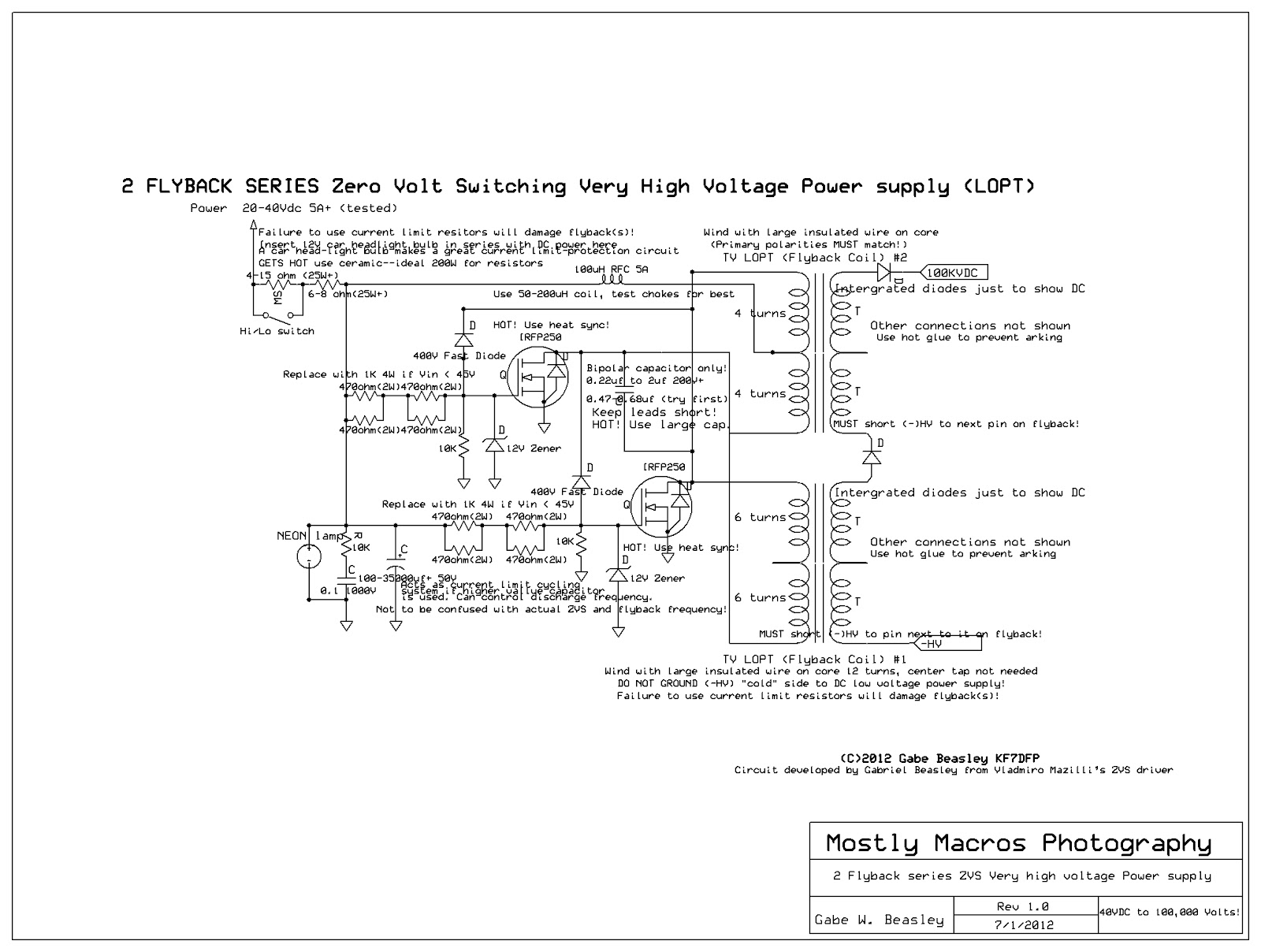
Very high voltage can be roughly measured in a simple way.  When an arc begins between two points for every 1mm reached the arc has about 1000 volts or 1kv.  This however only tells you roughly how many volts you have.  So if you have an ark this size, say it starts "cracking" at 75cm--you for sure have at least 75,000 volts.  Many stun-gun companies have made outrages claims about voltage that I put to the test.  In recent years they have come up with new designs to reduce "kickback".  This required reducing the voltage.  That is actually not a problem at all, since the good models traded voltage for current. However they did not want to say that the new models were less volts then the old ones!  So they usually lie, and thus many stun-gun companies (Not TASERS) claim to be capable of "millions" of volts. This was just a ploy to make them sound more powerful.  My tests showed they range from 30-60kv.  Most quality models are around 50kv just like a police TASER.  Police should not be overly afraid of these devices as shown on some police shows--the TASER they probably carry is almost certainly more powerful then even a "7 million volt" stun gun".  Electricity is about the CURRENT (measured in amps and milliamps), how many milliamps (ma) the electricity is at.  You can get over 100kv from a blanket!  However, it won't even knock you down.  This is because the amperage, the current, is very very low.  It's a bit like a small fire-hose and a pressure water gun.  Both may shoot water just as far, but the fire hose pushes 100s of times more water out then the water gun.  I used to have a stun-gun that definitely approached 100kv but I cannot find them anymore.  This does not mean it will be less effective, as the 40-50kv has far more "knock down power" if done right--then the old higher voltage models that would not only shock an attacker but shock you as well!  Most of the new ones are built better. Generally on line, you get what you pay for if you go to a Stun-gun site. Kickback through the batteries, switches and even plastic is why the voltage had to be lowered--the ones that are really high often would shock the person using it at the same time as the attacker, not as much, but this still rendered it nearly useless.. I doubt you could build a useful 200,000 volt stun-gun. It is just not piratical to build something that produces 100,000 volts or more in a very small package!  Most people are under the false assumption that voltage is what hurts and can kill.  Current and frequency are two other very important factors, the most important being current (ma).  A similar "kickback" situation happens with this ZVS I built.  The high voltage goes back into the DC supply which thankfully arks to the metal chassis and close wires rather then totaling parts and destroying itself.  But this is not good, if your ZVS has arcs you don't want, you need to fix it or parts will fail far faster. This ZVS definitely pushes the limits of TV flyback technology.  It is not possible for me to earth ground it despite a large series of MOVs and snubbers.  It seems to be impossible to ground TV flybacks tied in series without overloading the entire system if it is a ZVS. A recent test damaged this unit when I was making arcs.  I was able to repair it, but I will not try ground it again!  The voltage jumped so high it arced into the primary insulation in about a second. It was rated for hundreds of volts.  I hoped that if I could ground the DC low voltage and the HV things would be stable, but as with my 555-Mosfet system--the voltage output increases with an Earth ground (that is good and has a different effect for the 555-mosfet system--more power and almost no kickback!).  Interestingly, the 555-mostfet system actually had to be earth grounded if I did not run it off batteries. Where the ZVS can't be as it is a two phase resonant circuit (I use the term "phase" loosely here as a pulsed DC term). Two mosfets power each side of the same primary coil with a center tap in a basically "push-pull" cycle.  The 555-mosfet system has only 1 line to the coil other then the ground, one phase to one side of the primary and the other to ground.. This makes it possible to earth ground it nicely, including AC/DC flybacks.  However 555-mosfet systems can get hot very quickly and are not as efficient as ZVS systems. The single phase synthetic aspect of it makes it very stable when grounded to earth with a 3 prong outlet.  This lets it run ignition coils and just about any kind of transformer without kickback problems!  There is never any kickback noticeable, even when drawing large arcs!  I am working on a way to build a 555 driven dual flyback system.  I already have done it, but with just 1 mosfet running both flybacks the voltage gain was only about 10kv over the max output of 1 flyback--not worth it.  I am almost sure the flybacks will have to be in oil if I really get it going, say with more mosfets.  With the ZVS, no matter what I do, some of the power arcs back into the cores of the flybacks and wires.  The only way to keep a TV flyback ZVS stable is to power it off batteries or not ground any part of the HV or low volt DC while I keep things balanced with insulation.  I also cannot hook it to any large objects that would become a floating ground themselves.

(More pictures coming soon)

I am trying to overcome these problems to find the best supply for powering a 300-500kv+ Tesla coil I plan to build when I can afford it.  Generating voltages this high is a complex science with many problems to solve that are very similar to radio frequency devices. Putting the flybacks in mineral oil may allow them to become more stable but I doubt it would solve the problem of kickback totally.  If you build a flyback system or ZVS of any kind understand that your dealing with far more complex factors then low voltages.  The voltages produced may also exceed what the flyback diodes can handle and destroy them that way.   A flyback I was using died from the overload so I since refuse to remove the (50W) 12V car headlight (you can use halogen bulbs or 12V 50W bulbs from nearly many stores) to protect the circuit components and also give a visual warning if something is overloaded.  Since this ZVS system runs on 22 or 44DC volts--a dead short may blow the bulb like a fuse--but that is far better then blowing both mosfets!  It took me days of experimentation just to figure out how to modify the ZVS to work with 2 flybacks and solve the problems.  I was compelled to figure it out as I read on line that it was "impossible" to connect DC flybacks in series and so I wanted to prove them wrong and get more real-world experience before I start on the Tesla coil which is my current goal for all this high voltage stuff.  For Example, I had to completely coat the bottom of them with hot-glue so that the 2nd flyback does not arc.  Don't arc a ZVS like this for a long time.  As I say I also recommend always using one or two 50W 12v light bulbs in parallel to protect your mosfets should anything go wrong, this also acts as a second fuse and trust me, saves you lots of money in parts while cutting down very little on actual output. If you don't--if one mosfet goes it will short and probably fry, taking the other mosfet and possibly other parts with it!  You can also see your current draw by how much the light bulbs light-which should not be very much.  A quick way to know something is wrong and what might be wrong.  I also have a fuse on the 120vac mains--this is VERY important.  If you don't use a ballast bulb like 12v 50w bulbs-- you will blow a lot of parts before you get it right!  I bought a pack of 3 at a Safeway store for less then $10 and now use them in all my HV supply experiments.  I also use current limit resistors to further keep things cool and not overloaded.  The large power mosfets (IRFP250) do not get very hot so only small heat syncs are needed.  This is a great supply for plasma experiments and amazing your friends as well as getting photos of awesome arcs and there effects.  Smaller versions could power lasers and other very difficult and advanced projects.  I can adjust it from about 20kv to nearly 100kv with 4 different settings on the DC supply that I built to power it.  It costs about $400-500 to buy a supply that can do the same thing on line.  I can't afford that.  Being a licensed amateur radio operator and an amateur scientist, it has been a lot of fun since I have been seriously interested in electronics for more then 20 years.  Of all the 100s of projects I have built, this is surely one of the most interesting and fun.

Here is a 35mm picture of the inside.  Everything that I think is really important I photograph in 35mm so that I will have a negative of it.  I figure that some 90% or more of digital pictures taken today will not survive more then a decade.  Many will be lost, deleted or thrown away and someday history might well have seriously strange gaps during this time because digital photos and the media they exist on may not survive future world events and changes.  Even if it does, CD, memory cards and hard drives today would be very difficult to figure out by some future technology if we ever rebuilt after a worldwide natural disaster or something.  Negatives and film are understandable even to a caveman who can see the image at least--it would not take long for someone to invent a way to process and enlarge film again.  I cannot say the same for our very oil-dependent electronic technologies.  In a rebuilt society computer programming might be very similar but not the same, lots of very complex things would have to be cracked to figure out an SD card or a CD/DVD.  Most likely the people trying to uncover what it is would ruin it by trying to figure it out long before they ever could figure out how to read it.  Nothing is like a good old negative--anyone can see it and you can process it into a print with relatively primitive technology that will almost certainly be around as long as human kind will be no mater what the future is like.  Film is forever as long as you take care of it.  NEVER throw away your negatives.  People lots many important photos because of that.

This is a typical ignition coil being operated off of about 12volts with a 555 timer circuit and a power mosfet. The mosfet (IRFP250) has no heat sync only because I knew I would only have it on for about 10 sec.  Any longer and the mosfet is in danger of overheating without one. When using mosfets, great care must be taken in keeping them cool and protecting them from high voltage.  I use several circuits to reduce kickback volts as well as fast diodes.  The 555 timer chip is adjusted with 2 potentiometers (I later add much better ones for fine and easy adjustment and build this into a plastic tray with a glass bottom).  This is at least 20-30kv.  Some ignition coils have been known to kick out over 100kv when pushed past there limits. They produce dangerous voltages at dangerous frequencies to the human body--about 70-90hz or so I would guess. They can handle a lot more abuse then flybacks but too much and they will either fail and simply arc to themselves.  They are already full of oil but putting them completely in a vat of inert mineral oil may make it possible to run them harder.   If you value your coil you won't overload it and make sure it does not get too hot.

This is a test that Tesla often did to impress many of his friends.  Using the ignition coil which is a form of Tesla coil in a way-- I lit up this florescent bulb just by holding near the coil.  I later got it even more bright without even getting close to making contact using my homemade flyback!  A WARNING HERE Ignition coils produce not only high voltage but high voltage at a frequency that is about 80hz or so.  That's just about perfect to disrupt the human body!  You can get electrocuted and die with ignition coils, they are generally more dangerous then most flyback coils.  Flybacks operate just above human hearing range all the way into 20kc or more.  They thus are less dangerous but can still store quite a charge since most of them include diodes to turn the HV into DC current for the picture tube.  Today it is rare to find an AC flyback.  They are not actually really true AC in a total sense but they end up producing it when charged with pulsed DC.  The best flyback for most things is an AC flyback. You want an AC flyback as the current will tend to ground to anything really easy and not store up like static to bite you.  The high frequency then won't really shock you anymore--it feels like getting an RF burn if it does.
The Picture above is a DC flyback.  It has an HV diode in it, or more then one, which turns the output into DC which can be stored up in a capacitor easy and is best for tube applications like a TV--or with the right homemade capacitor--super-arc!   Unfortunately very few flybacks can be converted to AC.  So I built my own--since plasma displays like an argon filled light blub (most incandescent clear large bulbs and some soft white ones) need this in order to look cool and let you touch the output without feeling a really nasty shock as the voltage builds up and then discharges despite the frequency of the primary.  As you can see--I have now built my experiment unit complete with a white box that has a 15 turn variable resistor in it which lets me fine-tune the output and a fast tune control for quickly shutting off the mosfet.  A 50W 12V bulb protects the mosfet and flybacks from too much power.  Without the bulb, I'd have blown 40 mosfets by now!  With it, I have not blown one in this system and I use it the most out of all my HV gear.  The power supply is an old DC supply.  The 555 is powered by a 7805 voltage regulator to insure that I always get the same performance even if I change to batteries or change the mosfet's drive voltage.  It might be best for me to change it to a 7812, I just did not have one immediately on hand.  I will test that eventually.

This "kit" has a glass bottom to prevent arcs and burns.  It is the top of an old scanner I built as a coil experiment kit and it is very useful, it can operate from about 30hz all the way up to nearly radio frequency.  So I can power nearly ANY transformer made of anything.  I can also add voltage, so if the 15volt main supply is not enough, I can add to it without effecting the 555 up to whatever the flyback and mosfet can handle.  It has MOV's for HV kickback protection, as well as a circuit NEON lamp and other kickback resistant circuits.  The dip switch panel--red on the bread board--switches what "band" of frequency it is operating at which depends on what type of coil I am using.   The ballast current limiting 50W 12V car head light is just out of site.  This surprisingly does not drop or effect things all that much, it's really hard to tell since it will let 4 amps through it before it gets bright. I can also use this same system to drive any DC motor that will run on 12-14volts.  I have also added a "high/low" switch that gives me the option of running the mosfet at about 30VDC.   It will pulse drive DC motors and acts as a precise motor-speed controller without any adjustment.  The mosfet is further protected with ultra fast diodes.  A good heat sync is VITAL!  Even with a large one, a computer fan may be needed--always keep a watch on your mosfet temp--if the heat-sync is too hot to touch it probably needs to cool down or you need to reduce current draw.  I can do this with the control dials or a power switch.

This is a "Jacob's ladder" I put together with a simple 1 transistor flyback circuit.  But it works well, especially when I made some changes to it.  First off--don't use the poor 2N3055!  I tried that and it did not work well (compared to mosfets)--they over heated or burned out very fast.  For a good transistor order an HV horz. transistor online or just pull the NPN out of an old TV or monitor--you should find a large black power transistor with a heat sync on it in nearly every TV near the flyback and hooked directly too it--this is a high voltage horz. transistor. You can get your flyback and transistor from the same TV!  It is almost always an NPN that can handle voltages so high that arks can happen between the leads and it still does not fail!  You can build a Hartley resonant oscillator with it--this is probably the quickest and most easy way to produce high voltage with TV flyback.  Only a few parts are needed and you can get over 30kv! If you get the coils right and use the flyback's internal coils--you can get awesome arks.  I built two supplies this way, one I still have.  It's great for a quick spark circuit but this design has it's limits and requires at least 24volts to really put out nice arcs.  Beginners seem to be afraid to use any of the flybacks coils and often I see on U-tube people breaking them off :( Don't do that!  There is no reason too.  You can cover it with a $5 hot glue gun and $2 worth of glue.  This makes it possible to stop unwanted arcing and lets you chose to use them in the future.  If you can isolate the primary--which is not that hard--you can use a home made winding for your feedback and tune it until you have the optimal frequency.  This takes time and a coil that has room for some extra windings but is really worth it.  Using the coils built into the flyback (finding the right ones by testing it very current limited so that nothing gets fried) is a better idea for this circuit then trying to drive a short homemade primary as many online articles and schematics show.  I think you would need about 50turns or more on your primary if you really wanted to do it this this way. I did away with the need for a homemade winding all together eventually and just used the flybacks own built in coils, after all that is what they are for!  With a ZVS you definitely want to use your own primary for a number of reasons, first being the amount of power you have to put into the flyback and need for a center tapped winding not connected to any high voltage.

WINDING YOUR OWN FLYBACK
IT CAN BE DONE--like an article said somewhere you can't hook 2 flybacks in series, I also found one that said you can't build your own flyback!  I challenged that too.  I built a flyback.  It's not quite as powerful as most TV flybacks, but it's AC output makes it great for arcs and plasma displays.  The above picture is what NOT to do!  This was an early attempt I tried to show why you can't just lump on wire.  Sloppy coils might work to some degree in mineral oil, but messy windings don't work well and enameled wire has no insulation to high voltage so immediately it will start arching to itself in a normal environment.  I never found out what this transformer could put out.  So I re-cycled the ferrite core and wound one the right way.  To prevent internal arcing you put layer upon layer, each wound the same direction and in the same way.  After each layer you lay the wire across and make the next  winding with a layer of electrical tape or better.  Use double sided tape to keep tiny magnet wire neat and stick to the coil.  It takes time, and concentration but it can be done.  Laminate each layer with Teflon non-conductive tape or electrical tape, 1 or even 2 layers.   Put as many turns down as you can at first--then work your way up.  This one has about 12 layers.  Starting at about 30-40 turns the last layer only has about 15-20 turns.  Each one has a few less and is covered entirely with tape so that arcing is prevented.  BE SURE to use some double sided scotch tape or folded scotch tape to stretch across where you wind each layer and wind it tightly.  This will give you an edge when winding by hand very small wire.  It won't come lose as easy and it will be far more easy to guide the wire on as it will stick to the tape and stay in one place.  If you do it right and you have big enough core--you could build a very large flyback this way.  Possibly up to 50kv or more!  However, it may take 30-40 layers for that many volts.  Just as long as the insulation is good enough--to go higher then some voltages you need to submerge the coil in mineral oil. 

10-12kv Homemade AC flyback coil--(GREAT for light bulb plasma displays or NEON signs!)
Be sure each winding has a cover of electrical tape that totally covers it up.  All the way to the side.  This stacks them like batteries, so they won't arc to each other.  Then you just have to use hot glue to make sure the ground (which will be the inside lead which is the first wire from the bottom winding) and the hot lead--don't come too close to each other or the core.  Of course wind you coil around a plastic tube that fits into your flyback core. This could be a chapstick container or something.  It is critical to insulate the coil from the core to prevent arks. I used the core of a dead TV flyback I had.  The core comes apart easy but be careful as they are about as fragile as glass and too much knocking or even force can cause them to crack to peaces.  When done, replace the metal bar or just use tape to secure it and hot-glue the rest.  Hot glue does not even show conductive effects at 100kv!  I have found it invaluable in working with high voltage projects.  Here I had not even finished putting a HV line on it yet, your ground lead can be any old trustworthy wire--and for an AC flyback should be grounded to your power supply and Earth ground if you have a 3 prong outlet and are running on AC power.  The upper hot lead then should be hot-glued carefully and securely somewhere on top of the last winding--that's the one with the most HV--so it won't arc.  I chose right in the middle.  Cover it all in hot glue and it will be insulated.  Then use hot glue to keep the tape in place and from possibly arcing out of the last few windings.   DO NOT connect the core to ground or HV.  And use a HV wire rated for the voltage you think your flyback is.  It's best to go high--such as good ignition cable or other HV cable. This way you won't have problems with possible burns through the wire.  The core should float since any potential might cause arks to fly out of the sides of the coil if you don't have enough tape and hot glue.  No enameled wire should be exposed, and pay close attention to the winding process.  All coils must go the same direction and NOT back and forth, just one way.  Right or left every time on every layer.  Then I used some good wire that can handle high voltage for my high voltage output. For this small one, my first one, I only needed 15kv--but I still get leakage.  So I should have used full 20kv cable or more.  Ignition cable is great for this too.   This is a simple idea but it's difficult to get done.  They used to layer flybacks like this back in the 1950s and dip each layer in an insulating solution.  Tape and hot-glue will work fine.

UNEXPECTED SURPRISE! --MAGIC EYE TUBE
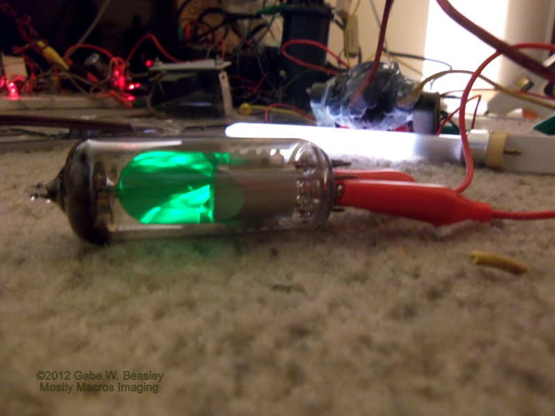
I had a Russian Magic eye tube that did not work :(  Magic eye tubes are small tubes that used to be used in radios and audio gear to show tuning.  They glow green and work just like a tiny CRT.  Phosphors convert low power cathode rays into light.  The filament no longer would heat up in this one so I thought what the heck do I have to lose?  I hooked it up cold cathode and to my amazement it came on almost as good as if it were being ran with a hot cathode and all the right connections!  It was also just as bright.  I was amazed that I could even get it to respond, although not as well, to the grid.  It definitely works this way.  I really did not think I could get a magic eye to work cold cathode!

A SERIOUS NOTE HERE ON X-RAYS and high voltage in vacuum and radio tubes:  At voltages below 15kv X-ray radiation is not really a worry since any produced will be high UV or "soft" x-rays and probably unable to even penetrate the glass of the tube.  HOWEVER at only 20kv you run the risk of producing DANGEROUS X-RAYS.  And don't get any ideas, they are NOT enough to take pictures or expose film.  Such experiments are extremely dangerous and I have seen too many fools try to do this, it ends in a wasted effort, fried tube and possibly worse.  NEVER attempt to produce X-rays or operate tubes that are marked as x-ray producing tubes.  Without the right and very complex specific shielding you will get very sick, burned or even cancer.  Look on line for what these burns do!  I bought a Geiger counter as part of my gear to make sure none of my experiments generate dangerous levels of x-rays or dangerous radiation (ionizing radiation).  This is a good idea for anyone working with tubes, tube lasers and high voltage for any reason.  Even though I knew I was only at about 8kv with this tube, I checked with my RADEX Geiger counter.   But since this type of tube is probably not lead glass and most radio tubes are not, I wanted to be sure.  Be aware that when working with many flybacks and tubes if you try putting high voltage directly into them for any reason.  If you are using a tube HV rectifier, make sure it's in tolerances and check for radiation.  If you detect any--you should stop using the tube immediately!  Never arc high voltage into vacuum tubes or radio tubes. This leads to fast and permanent damage to the tube and could be very dangerous.  Tubes are rare, most are not made anymore, you should never waste them.  And high voltages in flybacks will blow up filaments and destroy grids.  It does not look cool and it happens very fast, just an instant dead tube.  I once tried to use an old radio type 76 as a plasma display tube, and found nothing happened except an arc bit right through the glass and shocked me!  Today that tube would be worth $20! They are usually not designed to handle more then a couple hundred volts.  Not only that, the filament was ruined and the tube was now filled with regular air.  The same thing happened to me with DC fly-backs and florescent light bulbs and other small potential arc-display tubes.  You can't make a plasma a display out of a vacuum tube- what goes on would not be visible human eyes so no "cool" video either!  NEON and other gas regulator tubes make great and safe plasma displays however--be sure to use a large resistor (1-2meg) as a current limit (then just wrap the high voltage wire onto the tube and often they will light up).   Some people mistake old TV rectifier tubes for "X-ray tubes" as there is a warning on them. They are actually made of lead doped glass and do produce a small amount of rays so often they are shielded inside the TV.   Not enough to expose film--just be dangerous if you spend too much time near them. This is why your mom said don't sit too close to the TV (if your old enough to remember that)!   If you are using tubes with high voltage for whatever reason--it is important to be aware of possible x-ray issues and it's a good idea to get a Geiger counter (no mater how rare or unlikely it's good to be sure).  Although expensive ($170+)--they are always a good peace of gear to have and know how to use (this takes some learning) in your home lab.   Most plasma displays and nitrogen filled light-bulbs, mercury vapor lights & florescent bulbs or neon bulbs generally do not produce harmful x-rays.  It never hurts to test every type of plasma display and tube you use--if you pick something up DON'T USE IT.  Keep your counter a foot or two away from the source to prevent false readings from HV.

EM SERIOUS NOTE:  As I already mentioned, arcs and high voltages produce RF energy in the EM spectrum.  This is not dangerous to people--except if you touch the hot lead of an AC flyback and feel an RF burn!  HOWEVER it can be very dangerous to passing aircraft and other services. I know some people would love to make a spark gap transmitter. :(  I would like to be able to build the same radio set from the days of Titanic--but as far as transmitters go, spark gap transmitters put out too many frequencies to be filtered and thus were quickly outlawed everywhere back in the 1920s when tube oscillators replaced them as a means for far more conversations to take place at once and the use of higher frequencies.  We must respect the electromagnetic spectrum as these arcs can cause massive interference on TVs and other devices.   I live in an area where someone's ionic-air filter (that's my best guess) makes working 10meters almost impossible!  This is very irritating and technically illegal.  I don't know where they are, but that's my guess what it is since it's on most of the time. Many of those produce small arcs and harmonics over a very wide bandwidth that sounds like noise.  Never put an antenna on a arc or spark gap and keep leads to them short.  Spark gap transmitters might look cool but there are plenty of other ways to make awesome projects and transmit clean signals legally.  Aircraft use many AM and low frequency systems that could be seriously effected by spark gaps if your arc is connected wrong.  Always be aware of how much electrical and other interference you may be putting out. You don't want to jam up everybody's TV/radio even in a digital age this happens.  The FCC will break down your door if you mess up an aircraft Nav. beckon signal.  Don't put long leads on stuff that will arc and take care when experimenting and test for all forms of emissions you might suspect could be a problem, use a shortwave all band radio and an EMF meter to see how much energy you are giving off and how far it can travel.  Proper tests are very important if you are going to experiment with electronics and other devices.

HIGH VOLTAGE CAN KILL!  If you have a pacemaker you should NOT experiment with ANY of these devices or high voltage as it may be disrupted.  ALSO flyback transformers can be very dangerous but probably will just give you a very painful shock or burn. NEON SIGN transformers and microwave oven transformer have there uses but they don't give you a seconded chance to remember that pain!  A NST or MOT can kill a young man in good health instantly!  BE EXTREMELY CAREFUL when working with high voltage and always unplug when not in use or working.  Be very aware of capacitors--as they can also be deadly.  Even a camera flash can hold enough of a charge to kill if it is big enough.  I once blew a 100W light bulb with a capacitor from a medium camera flash. And I nearly died when I was only 9 years old doing my first experiments in electronics without knowing many of the basics.  I got myself hooked to a 600 volt transformer that was inside an old electric fence system.  It produced enough ma to kill someone!  The fence itself used a buildup in a capacitor oscillator circuit to produce a higher voltage in pulses which made it safer.  The 60hz direct output threw me across a room and left me unconscious for over 1min. I could not even move.  It took me a day to recover.  I was lucky because a friend pulled the plug, otherwise I'd have been killed due to a strange effect called being "hooked" when a charge at a lower frequency holds your body by moving your muscles (which are electric that's why they move when shocked--we all are powered by electricity!)  Electricity is dangerous--just because a transformer is small and looks safe or low voltage does not mean anything.  Be sure to be thorough about your work and tests to insure you live long enough to have fun experimenting!  --or just sit back and look at my pictures. :)

The 8-10kv flyback in action.  Sometimes a clear bulb will take up to 1min to start arcing inside.  I think that may be due to heat or some kind of buildup required in the gases.  Once it gets going it looks great.  The florescent lights are not hooked to anything, they just light up by being there.

A large glass bulb and a CFL used to light up area.  Note the small arc going to the bulb--a high frequency arc can totally change the amount of streams and activity as well as how it looks in the light-bulb.

The arc is not really big to brag about, but I did not build this coil for that.  It was built as a medium voltage coil for running plasma displays like the light-bulb and it does that well.  The ark is very bright, hot, and loud.  It can get up to 1cm or so.

(Image removed--really bad quality need to re-shoot--plans will be back soon with brighter images)

These are the basic plans I noted from an on line article and then changed a bit for my flyback.  Remember to only wind in one direction.  This one was a bit more complex then it had to be.  The basic idea however of how to wind is here as you can see with the coil layered diagram on the left top.  I drew these plans up a while.  The arc is very hot and will burn you if you touch the wire or the arc.  It also will quickly light anything in it's way on fire!  Plasma is the hottest state of matter--hotter then the surface of the sun.

One more shot at F1.8, when some incandescent bulbs burn out, there filaments knock around inside and if you can use that to knock the white dusting off of it--you can make an interesting new plasma display. I have gotten some of these types of bulbs to be nearly clear by working on them all day when I was a kid, just banding them on my leg or hand lightly but forcefully enough to shake off the dusting inside.

Recent Highlights

I have many electronics photos I want to publish but first I thought I'd show you some recent other shots I have captured.  This ladybug took off and with my fast DSLR and quick thinking I snapped this shot just at the right time.  This is not a stop action, high speed or burst photo.  When I have time and energy I have been spending most of it on my projects with plasma and high voltage devices.  For most of this year I have been working on ways to combine my electronics/experimental knowledge and interest with my photography in ways I have never been able to do before.

 "My Honey bee"
There are LOTS of honey bee shots since they are so common, however, I still try to catch a good one now and again.  It can be far more difficult then it looks.

This spider was making a very good living in the vacant lot next door.  She managed to catch everything from large moths to bees!  She is a web building species but in this case almost does not use one.  Rather she seemed to use a small amount of cob web silk and the plant as her web.  This may have been how species like the crab spider or yellow flower spider evolved.  
A look at her face on now, from lack of bulbs on her palps we can clearly tell she is a female.  You no longer have to use the back arrow to return to my site thanks to blog upgrades.  Now you can see all photos in a post at once as a slide show in full screen.

 Shooting RAW 16mp has been an awesome experience.  With my lenses, I have been able to capture better images and do tighter crops.  This fly stayed still long enough for me to take a closeup.
A Harvestmen. It was also walking around in the lot next door.  Harvestmen do not spin silk and have a single fused body.  They have two eyes and are not spiders.  They are however relatives of spiders, scorpions and mites.  They eat many things from vegetable matter to already dead insects as they search.  They have NO VENOM and are entirely harmless to humans--in fact they are a very beneficial species that often can be found together in large groups without conflict.

 This tiny fly is on the top of a typical metal fence.  It is only about 8mm long from wing tip to eyes.  I had to move very slow to get close enough to capture this shot even with a good lens.

 A dandelion.  I thought this looked nice and would make a good desktop background.

"3d effect"
 This is one of several shots I discovered how to take on my own with my TV.  Using a zoom lens and a very steady hand, I was able to give a truly strange superimposed 3d image.  I had to be quick to capture it before the scene in the show I was watching changed.
 Another 3d effect image.  No these are not double exposures.  That would not produce the lines as if one is moving towards the object on screen.  I was amazed that my TV and camera did well enough to produce these pictures. The TV is NOT 3D and obviously the old B&W TV show I photographed here is not either.

 I like this one the most since the sign in the top says "Electrical Engineering".  A subject I have been really into since I was 9 years old.  I built my first computer (similar to those used on the Apollo missions) when I was 11.  Many people mistakenly believe that the computers of that age were only as powerful as digital watch.  That is like saying an Iphone is as powerful as a super-computer! In a reverse sense.  The digital watch idea is totally false as digital watches cannot store data or crunch numbers, let alone multitask. Most of them just count and have a rudimentary micro controller for programming with only a four functions or so. Even calculator watches cannot store anywhere near the amount of data needed for a space mission!  In reality the computers used to fly the Apollo missions were about as powerful as a medium level good scientific calculator.  One that can be programmed and of course do math functions as well.  The computer was also very efficiently programmed and used--every bit of it's memory and ability was used.  Something we don't do today because technology moves too fast for us to even fully understand what we have and how far we can push both the hardware and software for highest potential.  We live in such a fast throw away culture it is very sad.  The computers I built and the Apollo computers used the 74181 ALU chips (predecessors to the CPU), diode matrix ROM and static RAM chips.  I used a 64k 6264 static memory chip to store programs as well as it's data (that's enough to store a large novel).  These computers were very complex with 1000s of individual wires and took hours to program by hand. When programed however, they can do several functions at once and also perform a surprising number of things.  With my unit all of it had to be programed in hex and binary using switches as I could not find the parts back in that time to build a better interface such as an octal keypad like the one on Apollo missions..  The output unit was one 7 seg. LED display per 4 bit data bus.  I could store 1000s of phone numbers and program the system to play them back when I wanted or program in math for the system to do with numbers limited only by how many ALU chips I used, such systems are great for controlling things as the clock speed can be slow and can even be stepped.  It was more difficult to make a mini-computer from scratch back then, or with the technology--as there were no easy chips that did it all for you.  I built ALU computers with as much as an 8 bit data bus and 2 64k chips, each 8 bits. One was used as ROM (as at the time I did not have an EPROM programmer) and was left on all the time with batteries on low power.  The other was RAM and used to store the functions and numbers in HEX I wanted it to perform.  For example I could program it to run a cycle of stored phone numbers indexed by memory so that I could use it as a Rolodex.  I could also store more then just 1-8 as there are 16 combinations of one nibble--which is 4 bits.  This included the octal letters and I could use them which were displayed as well to show what memory "bank" I was in.  It was an incredible accomplishment to build from scratch for a 12 year old and remains one of the most complex devices I ever built.  The Apollo mission system was about twice as big as mine in terms of processing power and had a better interface.  The most amazing thing was the fact that I did not get this stuff from anything more then a basic list of the functions in each chip. I had to crack each chip on my own testing one thing after the next and even had to figure out how to use CMOS chips such as the 6264 purely by experiments and not some book on how to do it.  Sometimes I only had pin-outs for the chips and a description of what it was.  I had been given a basic understanding of digital logic chips like the 7400 but my training at that point had not progressed any further.  I had no help on how to do this and of course this was way before we had any on line help or the internet either.  I was living in Hawaii at the time and got most of the parts from a local computer store that had a stockpile of older chips I was lucky enough to find.  It took me about a year to crack all these problems and my grades actually suffered for it sometimes--but I did it!  Sadly, all the notes and schematics were lost in our house fire in 2009 but one picture of one of these computers I built still exists and I plan to find and scan it in here soon.

I get tired of people who claim we did not make it too the moon.  Trust me--we did.  Even if I don't like the fact that we did, we did.  Skeptics have been invited to view reflectors the astronauts left behind and refuse to acknowledge that fact.  The most convincing evidence to me is that the Russians did not say anything. They monitored everything we sent to the moon and back via radio--and if there had been anything that was not coming from the moon or any spy with a leak, cold war tensions would have caused them to jump at the chance to make us look like fools for "faking" such a thing.  We could not have pulled off a hoax that good and have it last. We use mirrors left there to reflect laser beams so that we can tell how far the moon is moving away from the earth.  Currently, it moves away from us at about an inch and a half a year or so.  At one time, the moon was far larger in the sky then it appears today.  We must be VERY careful with what we do with the moon.  It is so important that I don't think it should be used for much and treated with great respect.  The moon is necessary for all life on Earth.  Without it, no life would exist due to many complex factors.

Here is the Buddha--all of them are thinking the same thing.  I shot these with a 50mm lens at f1.8 to get my depth of field very shallow and thus only show one Buddha in focus.  I have a few more but it was difficult holding the camera steady.

Back to electronics!  I got this AWESOME collection of tubes on line.  Finally I have a good number of tubes to experiment with.  I like building things with tube tech as a challenge and for better sound.  These are almost all from the mid 20s to early 40s.  It was an awesome find.  I have found several rare batches of awesome tubes for bargain prices in unexpected places.

Sunday, August 26, 2012

UNDER CONSTRUCTION

"UFO building"--Portland Oregon, during Occupy Portland movement
If you have made it here, then you have probably noticed what has happened to my blog, Mostly Macros.  The blog which I have been building on for over 7 years was destroyed by an unknown problem.  Currently Google has no comment despite my repeated requests.  I figure it is most likely that my email address was hacked or hijacked somehow.  This is a big loss--100s of pictures, and years of work gone forever since my wife and I lost nearly everything in a house fire in 2009, including many of my pictures.  I refuse to be kept down however, I will continue to post here at this site as I collect and re-build as much as I can with new and older pics.  I still have 1000s of pictures I want to share.  It often takes an average of 1 hour per picture for me to upload when you count all the other things I must do.  So give me time to rebuild--and you will see some new and interesting stuff here.  This is the same Mostly Macros, but a new blog had to be created and I see it as a new beginning.  The first Mostly Macros blog got over 44,000 hits before it was tragically shut down for yet unknown reasons.  I still have no word from anyone as to why the account was disabled.  According to what I have heard, it was probably someone trying to hack my email address and so Google stopped it by shutting down the account.  I have been told if you want to keep your blog secure, change your password every month.
--Gabe Beasley
Mostly Macros photography
KF7DFP <--ham radio call sign

This blog is UNDER CONSTRUCTION so please forgive errors and things not yet setup.

I am not one to give up.  This new site "Mostly Macros 2012" is going to be better then the first one I think.  I took this shot in a mirror with my D7000 a while back.  I used a manual 50mm lens f1.8.  I have taken a lot of pictures and done many videos, but due to how much work it takes I have not posted as many as I wanted.  I will do what I can to bring you new and stunning images that I catch with my lens.  I will also begin to talk about my other big lifelong interest, physics and electronics.  This is NOT just an electronics blog--many subjects and pictures will be covered here.

"The ark"-- My 100kv power supply throws a nearly 4 inch ark with ease continuously.  This pic is a snapshot taken from a video that I will eventually post on this blog.

The other pictures of my 2 flyback series Zero volt switching power supply will also be posted soon.  As well as videos.   The ark can reach over 10cm at full power.   That is more then 100,000 volts!   The supply can generate about 20,000 to about 100,000 volts with an adjustable power supply I also built.  It runs on 24 to 48VDC and produces enough power to do a number of experiments such as creating lasers and eventually a full indoor Tesla coil.  It may soon be the biggest "singing arc" on UTUBE!  I just need some parts, I plan to mainly use it for photo shots and stuff.  You can buy something similar for several hundred dollars. I built my own.  I modified a design on the internet after I read that it was "impossible" to use 2 TV flyback transformers in series.  I like a good challenge, so I developed this circuit which does just that and proves it can be done with incredible results.  I have an extensive background in electronics and already have drawn up the schematic which can be seen below.  The hand-drawn one is a bit better in my opinion but I figured this is readable.  It was my first circuit designed with this software.  Warning! This circuit is very dangerous!  If you build it--I assume NO responsibility.  Be careful!
Double click on this schematic to view.  Then use your back arrow to return to my site.  This circuit MUST be current limited or you will FRY you flybacks and worse.  I recommend using a 50W 12v lamp to act as a ballast and protect the circuit from overload.  This prevents it from pulling more then about 4amps.  At 40volts the bulb might blow like a fuse if a series problem happens.  Even at 50v, when normally operating it should glow slightly but not much.  This is a trick I came up with that greatly reduces the number of parts that have to be replaced when you are working with high current applications.  You can add more bulbs in parallel to increase current load limits.  Do not operate above 50volts.  It will run up to as much as 70VDC or so but not for very long!  My first attempt threw a 6 inch ark and then a flyback failed.  The 12V zener diodes and resistances used can only handle about 50volts.  Since I have no reason to go higher and the flybacks probably can't handle it--I will not describe the mods needed to try.  It is possible to push a lot more current and voltage out of the circuit but I wanted a stable and trustworthy HV power supply not the biggest ark ever.  Still, the ark is more impressive then most on the internet when it comes to home made HV without a full Tesla coil. The 12volt lamp which you should put in series with the entire circuit as well as some other current limiting ceramic resistors as shown to regulate power output.  The rest can be done with your DC power supply.  I just used a bridge and capacitor with a center tapped 50volt 4amp transformer.  It also has a series circuit that lets me cut down on current at the AC side so I have 4 different settings of HV output controlled by 2 switches.  If I remember I will post the power supply schematic once I draw it.  I have built many approaches to making flyback HV and every time I find a new one that is in my budget to build--I build it. 

I have also got very good results from a 555 timer that drives a 1 mosfet (pictures later) which I use to run an ignition coil or AC flyback for a plasma display.  However--the ZVS is probably the best circuit out there for building your own HV supply with flybacks and some other transformers.  It must be able to at least provide 15-50volts at 4amps.  Test using batteries--lead acid are good.  You need several amps.  This circuit can be touchy so be sure to build it on a breadboard first to work out any problems.  Keep leads short.  Incredibly, believe it or not, using a 12volt series 50W bulb such as a car headlight or one of those halogen lamps you can buy at just about any store ($8 bucks for a pack of 3) --does not reduce output much but goes a long ways to protect things in the circuit especially if something goes wrong.  The bulb acts like a pressure release valve so in that way it keeps things from getting out of hand.  Circuits like this can be difficult to get right, so be careful!  Order at least 1 backup part for every part involved.  This schematic is my take on the ZVS.  I could write a lot more about it but for now if you have any questions email me.  Videos and project pictures will soon be posted.  I was limited to show some parts with my software but this circuit does work very well.  Do NOT ark for more then a few seconds as it can damage the flybacks at these voltages.  Be sure to check temperatures of all parts involved.  The primary windings must be insulated wire and make sure NO arching happens with hot-glue or mineral oil.  This circuit can be ran for a long time on low power, but at full power it should not be operated for more then 1 min or so at a time, especially if running something that uses lots of the HV.

 The "plasma force-field".  This is actually just a Jacobo's ladder running fast.  A Jacobo's ladder is usually two wires carefully put together.  The electricity starts arching at the bottom where there is a smallest distance between the wires and thus the least resistance. Once on, the arc increases in temperature and begins to make the air just above it more conductive then even the bottom because it is super heated. Thus just like any heat, the arc rises up the ladder even though the wires get farther and farther apart.  Once it reaches the top (or the limits of your voltage/current) the ark breaks.  This happens because the resistance becomes less at the closer space between the wires at the bottom of the ladder all over again when the ark is no longer able to seek a better connection.  At the top, there is no where else to go so the arc cannot rise anymore or even hold it's state.  Thus it breaks and again follows the path of least resistance which becomes the bottom of the ladder.  This is where the wires are closest together. This if done right, makes an awesome show as an arc will dance up two wires shaped like a V at different speeds and intensities depending on electrical conditions.  Many of them can be seen in older science fiction movies.   It was produced with a simple flyback driver that uses 1 high voltage power transistor from an old TV.  Many of these can be found in color tube TVs.   They are FAR better at running flybacks then the 2N3055.  Those transistors were built to run flybacks and handle really high voltages!  I also modified the 1 transistor flyback oscillator seen often on line to operate with the flybacks original connections and figured out the lead connections on several of my flybacks so that I can.  This is not that hard, just use a 50ohm resistor when testing to limit current so you can't damage the transistor.  Use only 12v.  I don't run the single transistor drivers off of more then 24volts.  The transistor can blow at 30volts and you must use current limiting here as well.  A reason NOT to break off the leads on the bottom of the coil!  They can be far more effective with some circuits at powering the flyback.  I have yet to draw up this schematic on computer, when I do I will post it if I remember to.  This was my work area, you can see a powerful homemade capacitor in the background.  It can store over 50,000 volts and throw a 3inch very loud ark.


 And I have not forgotten about spiders!  Mostly Macros 2012 will have many different kinds of pictures.  Just a few days ago I shot an interesting species I have not seen often here in my back yard.  I will be posting pictures of it soon.   This was a tiny spider I found a while back and photographed.  These shots were done using a D7000 and a modified extension tube macro setup.

 I photographed this small spider as she walked on my bed.


 Here is a good example of how small this spider is.   I believe she is a juvenile, so identification is difficult.

 Underside view of same spider, showing details.  Click on picture for full view.  To return to my site just use back arrow.
 A face on shot--showing her eyes up top as well as palps which are very female looking.  However, since this is such a young spider, it is hard to tell.

 AWESOME NEWS !
In 2012 this picture was printed in the Trimet event calender.   This marks my first time being published as a photographer.  A great moment for me.  Our local public transit system here really liked my shot and made it a nearly full page picture in December.   This is down town Portland Oregon.  1000s of people got this calender and my first published picture!

Much more to come, this is my first post.  I have a great deal of work to do to get this site going and actually looking good.  Please come back anytime--there will be more pictures and I can promise that the new Mostly Macros will be even better then the last.  It was a tragic loss, nearly 8 years of work--but this blog will grow.  It is not just a technical blog--you really never know what I will post here, from news to strange things.  It's just a way to show my photography and share my knowledge of the subjects I am interested in.